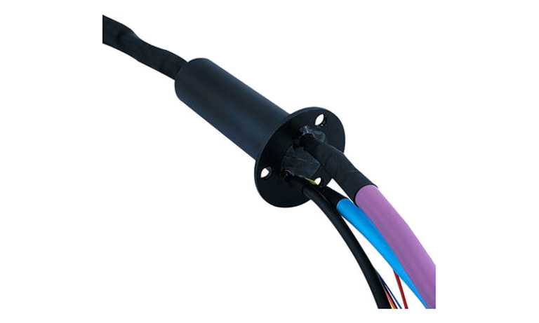
Most slip ring problems reported as “the unit is noisy” or “the signal drops out after a few weeks” are mechanical in origin. The contacts are fine; the housing has been pulled off axis by the very bracket meant to hold it. This guide follows the sequence that avoids it: interfaces first, wiring second, power-on last.
Two interfaces, one rule
A slip ring has exactly two mechanical relationships to the machine. The rotor is driven by the rotating side; the stator is held still by the stationary side. Everything below follows from one rule: only one end may be rigidly fixed.
If both ends are bolted hard to structure, the housing becomes a load-bearing member. Shaft eccentricity, turntable runout and frame growth are transmitted straight into the bearing and the contact stack. The unit still turns, which is what makes the mistake expensive: it fails months later, in the field.
Mounting by housing type
The method depends on how the unit is built, not on bracket space.
| Housing type | Rotor side | Stator side |
|---|---|---|
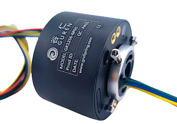
| Through-bore (GK series) | Tighten the rotor screws onto the equipment shaft | Fix the anti-rotation plate with screws or pins; keep free clearance between the plate and the fixed end |
| Flange mount (GKF) | Bolt the flange to the turntable | Same anti-rotation plate method, with clearance |
| Capsule / cap type (WX series) | Rotor torque is low: fixing the rotor lead is usually enough, or clamp the rotor with a sleeve to drive rotation | Insert the stator into a stationary sleeve and secure with flange screws, or fix the stator lead |
| Gas and gas-electric (Q series) | Rotor screw holes on the housing face | Stator screw holes; keep clearance between the fixing screws and the stator slot |
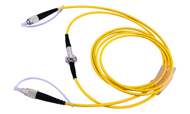
| Fiber optic (GX series) | Pin-driven end, with the limiting groove left slack | Screw-mounted end, or the stator body seated in the shaft bore |
The anti-rotation arm: clearance is the point
The arm stops the stator spinning. It is not a bracket and must never correct alignment. Two habits cause most of the damage:
- Over-tightening. A pin tightened against the housing preloads the bearing before the machine turns. Snug, then stop.
- Zero clearance. The arm should float slightly in its slot so runout is absorbed by movement, not by the slip ring. A rigid arm turns every micron of runout into contact-force variation.
On multi-channel fiber units the stakes are higher: the fork rods keying the rotor, typically 3 mm diameter, sit in a groove that needs generous clearance. Squeeze it and the rotor is pushed off axis, loading the fiber and the collimator gap.
Coupling the rotor
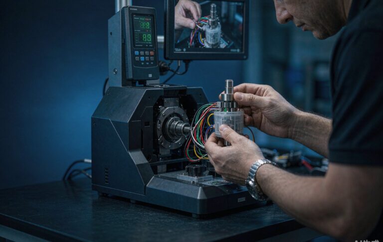
Seat the rotor on a clean, dry shaft with no burrs or paint in the bore. Draw it on evenly rather than tapping it, then check by hand that it turns freely. Rotational torque is low, so a stiff spot is easy to feel:
- Through-bore electric series: 0.1 N·m plus 0.03 N·m for every additional 6 circuits
- Capsule series, 48 V class: 0.05 N·m plus 0.01 N·m per 6 circuits
- Gas-electric units: under 0.3 N·m
A notchy unit at this stage is misaligned or took an impact in transit. Do not “run it in” — investigate.
Wiring and lead routing
Through-bore leads are AF200 17 AWG PTFE, 300 mm and adjustable at order. Capsule leads are shorter: 150 mm rotor and 200 mm stator on small-diameter series, 250 mm on 12 mm and larger bodies. Whatever the length, the leads are the weakest mechanical part of the installation.
- Leave a service loop. The lead must never carry tension,
- Strain-relieve at the housing exit, not downstream where the wire has already fatigued.
- Separate power and signal bundles and cross them at right angles.
- Terminate the shield at one end only to avoid a ground loop through the rotating frame.
- Respect the dielectric margin. The through-bore rating is 800 VAC for 60 s on power circuits and 300 VAC on signal circuits, so do not route a 400 V drive cable beside an unshielded encoder pair.
First run: five checks in order
- Hand rotation. Full travel both ways, drive disconnected. Listen for scraping, feel for a tight spot.
- Insulation resistance. At least 1000 MΩ at 500 VDC on through-bore power circuits, 300 VDC on signal circuits.
- Circuit mapping. Check every channel end to end against the drawing, and that none is shorted to its neighbour.
- No-load run. Several minutes at the lowest speed available. Stop if the housing becomes noticeably warm, current draw drifts up, or a data link drops packets.
- Load and speed. Only after a clean no-load run, apply load and step up to rated speed in stages.
Commissioning checklist
| Item | Accept when |
|---|---|
| Rotor concentricity | Free hand rotation, no notchy point |
| Anti-rotation arm | Snug, not preloaded, visible clearance in the slot |
| Lead routing | Service loop present, no tension, strain relief at the exit |
| Insulation resistance | At or above the datasheet value for the family |
Installation is also the cheapest place to catch a selection error: if the bore is a compromise, fix it at the specification stage, not on the bracket. The GK through-bore series lists the mechanical interface for each size, and the installation instructions cover the remaining housing types. If your mounting geometry does not match a standard unit, send us the drawing and we will confirm the interface before the order is placed.